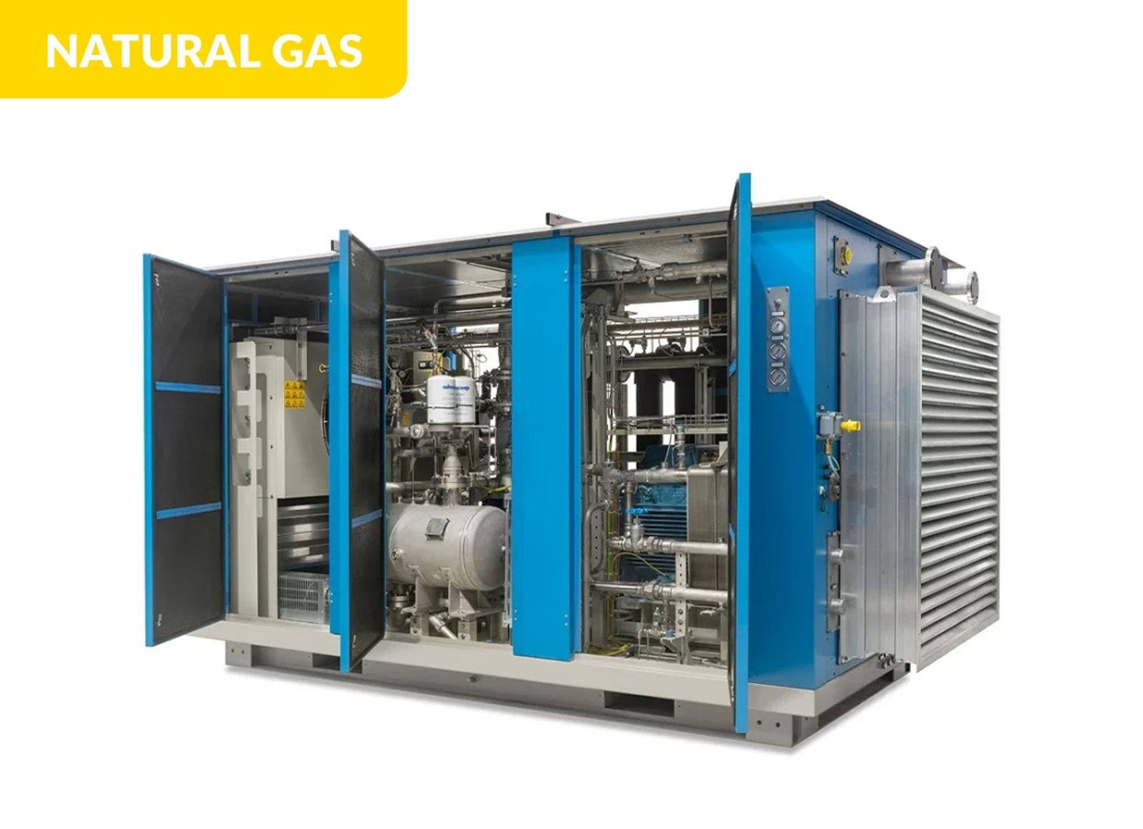
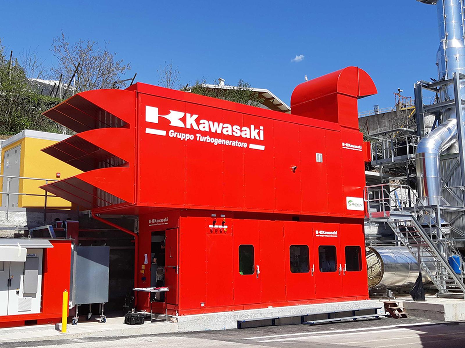
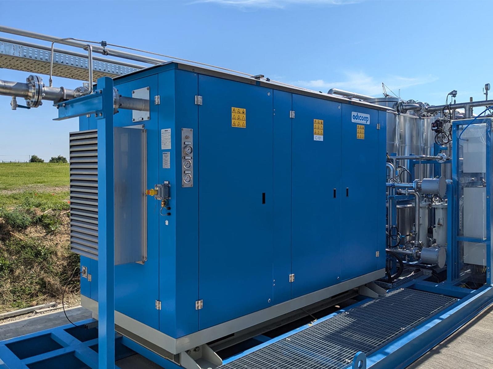
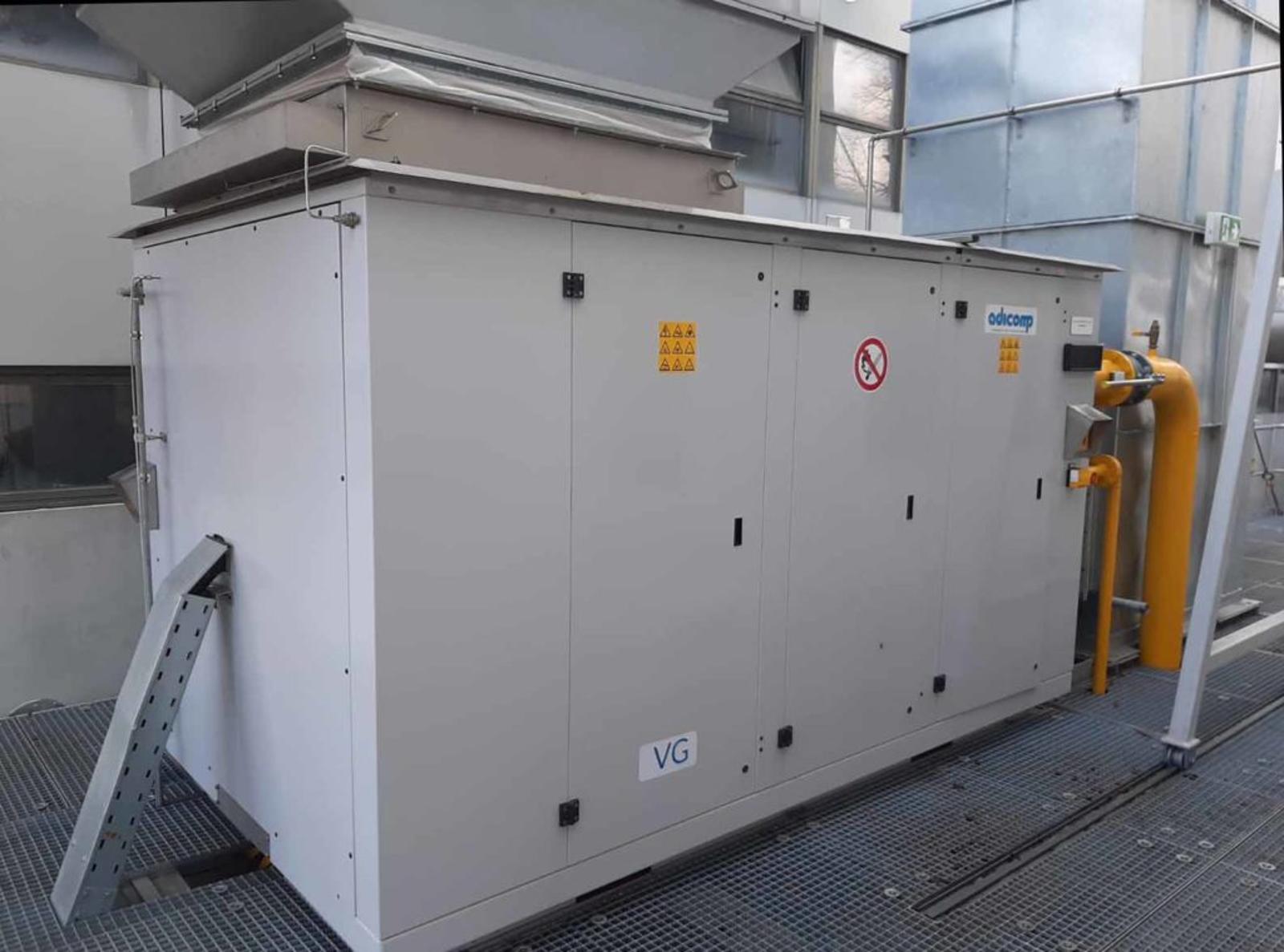
This compressor series is specifically designed to supply microturbines, turbines, boilers, and gas engines. Their purpose is to increase the inlet gas pressure, ensuring efficiency, compactness, and versatility for continuous and reliable operation.
- Microturbines feeding
- Turbines feeding
- Boiler feeding
- Gas grid injection
- Gas engine feeding